The best overdrive pedal DIY
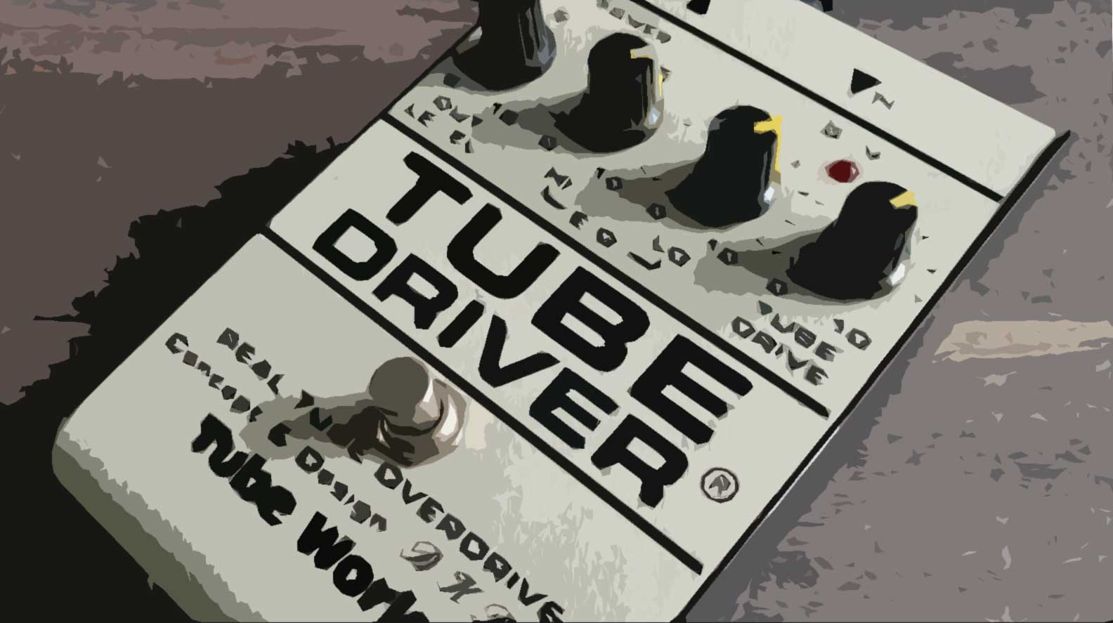
You don't often see the BK Butler Tube Driver on lists of "Top Guitar Pedals," even though you've heard its sound countless times. Why? It's simple: the BK Butler Tube Driver isn't a mass-market product; it's a handmade item by Mr. Brent K. Butler. The first models were assembled in his garage starting in 1975, and then Chandler Industries began manufacturing the pedal. In 1983, David Gilmour purchased a Tube Driver to replace his old Colorsound Power Boost, and since then, the "signature" Pink Floyd sound has been the Tube Driver.
Butler ended his relationship with Chandler Industries in 1987, but Chandler registered the trademarks Tube Driver and Real Tube Overdrive and began producing "improved" Tube Drivers, forcing Butler to stop making his own devices for a while. To protect his invention, Butler filed a patent application (number US5022305A) for his circuit design in 1989, and this patent is now available to the public. You can download and read it on Google.
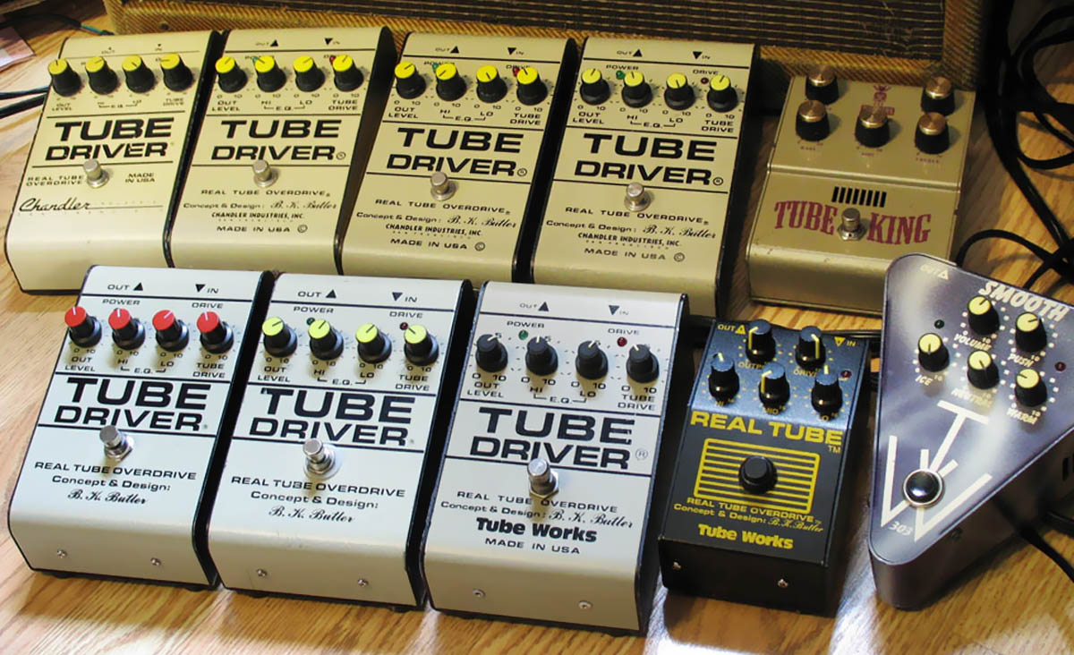
The top row (from left to right) includes the Chandler from 1988, three Tube Driver BKB/Chandler units from 1986-87, and the Ibanez Tube King (TK999US) from 1995. The bottom row (from left to right) includes the 2007 reissue of the BK Butler 911 Tube Driver, the 2008 reissue of the 911 with a rear-shift knob, the original 911 Tube Driver from 1994, the 901 Real Tube from 1987, and the 903 Smooth Pick from 1997.
Chandler tried to prevent Butler from making his Tube Driver and Real Tube pedals, claiming that it was their design and trademark, and even sued him. However, Butler won the case and returned to working on the original devices. Butler Audio Inc. was registered, but Butler never entered industrial volumes, remaining a unique producer of guitar effects and audio equipment for the chosen ones. Below is a video where the original Tube Driver is completely disassembled and there are examples of its sound.
In addition to Gilmour, Eric Johnson, Brad Whitford, Billy Gibbons, Joe Bonamassa, Joe Satriani, Kenny Wayne Shepherd, J Mascis, David Holt, Keith Urban, Andy Timmons, and other outstanding guitarists have BK Butler Tube Driver on their pedalboard.
So why isn't the BK Butler Tube Driver in the top guitar pedals and settles for 79th place out of 1975 overdrive pedals on the Equipboard Gear Score? The reason is simple: it costs a fortune. That's why there are very few people in the world who have heard this device live, which is why such opinions (mistaken, of course) are often found on forums: "BK Butler Tube Driver? Nothing special, just a regular booster!"
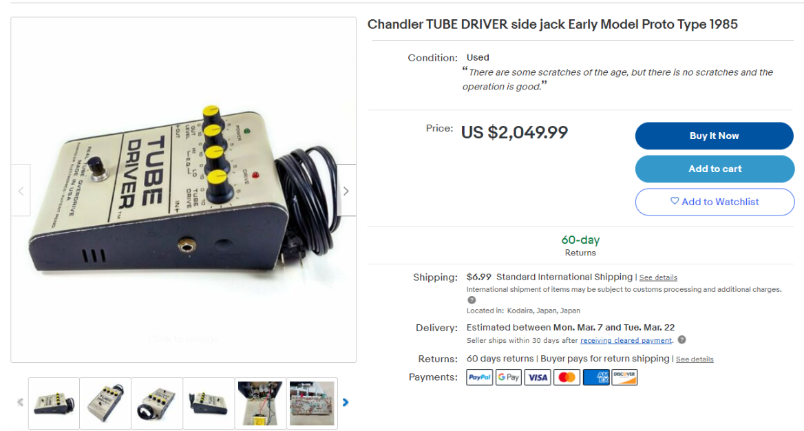
Prices for early versions of the BK Butler Tube Driver can reach several thousand dollars. The price for the modern version is much lower: $299 for the version with four knobs and $369 for the version with five. Of course, $70 for an extra potentiometer and two wires is completely unreasonable, but to be honest, if I were hand-building a pedal for ZZ-Top and Pink Floyd, I would charge more.
By the way, it's a good idea to build a pedal yourself. Let's do that.
Diagram BK Butler Tube Driver
The original circuit drawn by the author is attached to the aforementioned patent, so creating a clone is not a difficult task. Here's a brief quote:
Tube Driver has a unique construction compared to other tube overdrives. The use of the tube is completely different from the typical high-voltage circuit. Instead of using an external power source, as in modern pedals, Tube Drivers use an internal step-down transformer with an idle voltage of 15 volts.
The signal from the input jack first goes to 1/2 of the operational amplifier, which acts as a low-impedance input buffer. Then it goes to the other half of the operational amplifier, used as an inverting cascade amplifier. The operational amplifier is set to a high gain coefficient, with the gain level adjusted by a potentiometer at a maximum of about 350x. It is here that the primary distortions are generated before the signal passes through a pair of triodes in the 12AX7 tube. It passes through a resistive divider in the first half of the tube's inverting amplification cascade, then through another resistive divider before reaching the second amplification cascade. Instead of generating most of the distortion, the vacuum tube is used to color the distortion. The standard negative grid bias voltage together with the negative 12-volt voltage applied to the cathodes help the tube uniquely exaggerate distortions. The 12AX7 tube requires two different voltages - 12 volts for the heater element and 150-300 volts for the amplifying elements. The Tube Driver operates in "starvation" mode, with an anode voltage of only about 30 volts.
Above, I showed how many versions of the Tube Driver were released, and that's not all. In some years, only five or six devices were produced, but each one was "tuned" for a specific musician. In the early versions, which were not yet called Tube Driver, two tubes were used, and later, instead of a tube in the preamplification cascade, an JRC4558 operational amplifier was used, and later still, a TL072 from Texas Instruments. To jump ahead, I will say that I have listened to a dozen different operational amplifiers in the Tube Driver circuit, but these two left the most pleasant impression: the first has a fat and melodious sound, and the second has a wonderful bass gurgle. But the NE5532 from Philips, which sounds good in a regular amplifier, sounds completely unremarkable and unexpressive in the Tube Driver, and with this microchip, the Tube Driver is no different from dozens of other overdrive pedals.
It is necessary to understand that the Tube Driver circuit, as stated in the patent, was designed to win the case against Chandler. Apparently, the return to internal power supply placement was caused by this reason. As a result, the device became more noisy and had a very tricky grounding layout to reduce this noise. But why should we fight the transformer noise with the layout of components and wire placement when we can simply remove the transformer from the housing? I have tried both options and will say this: with an external power supply, there is no noise at all, so I recommend using an external power supply of 12 volts AC.
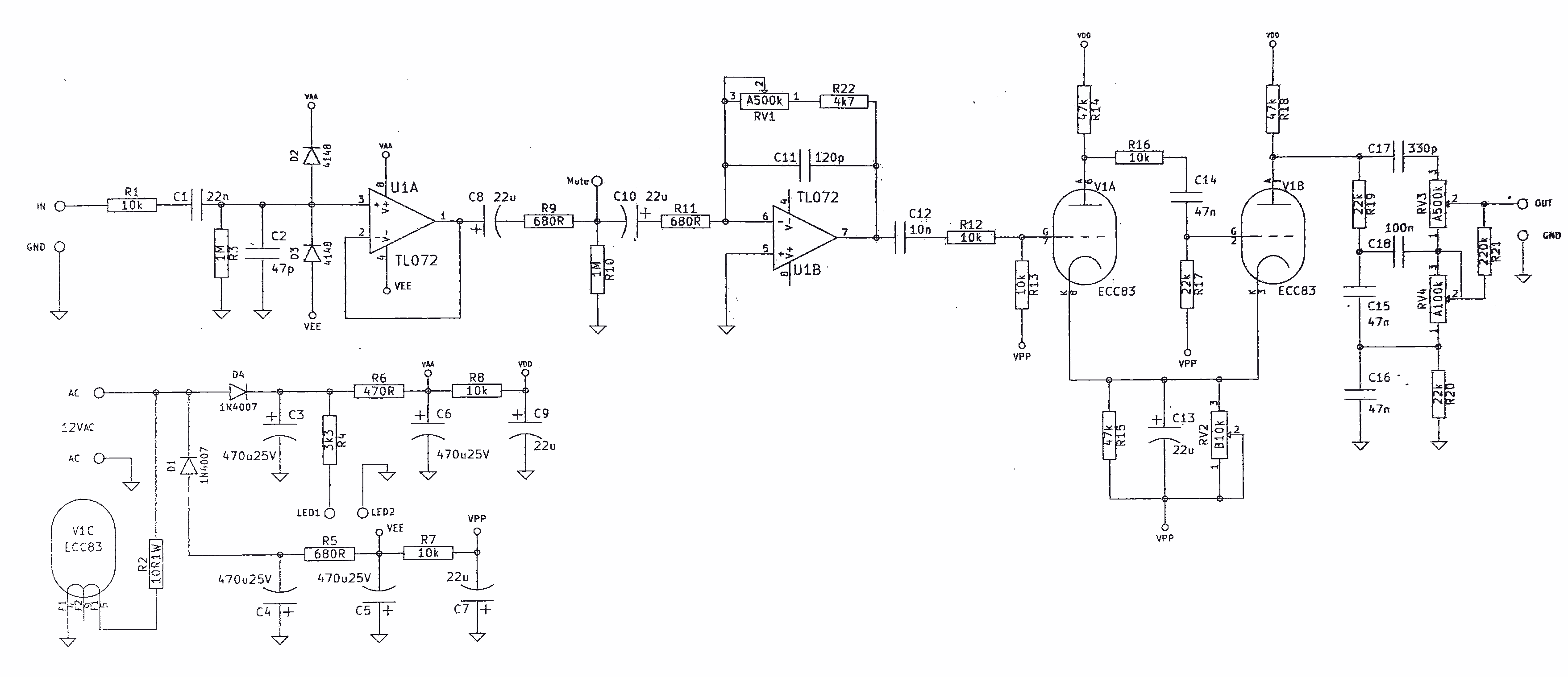
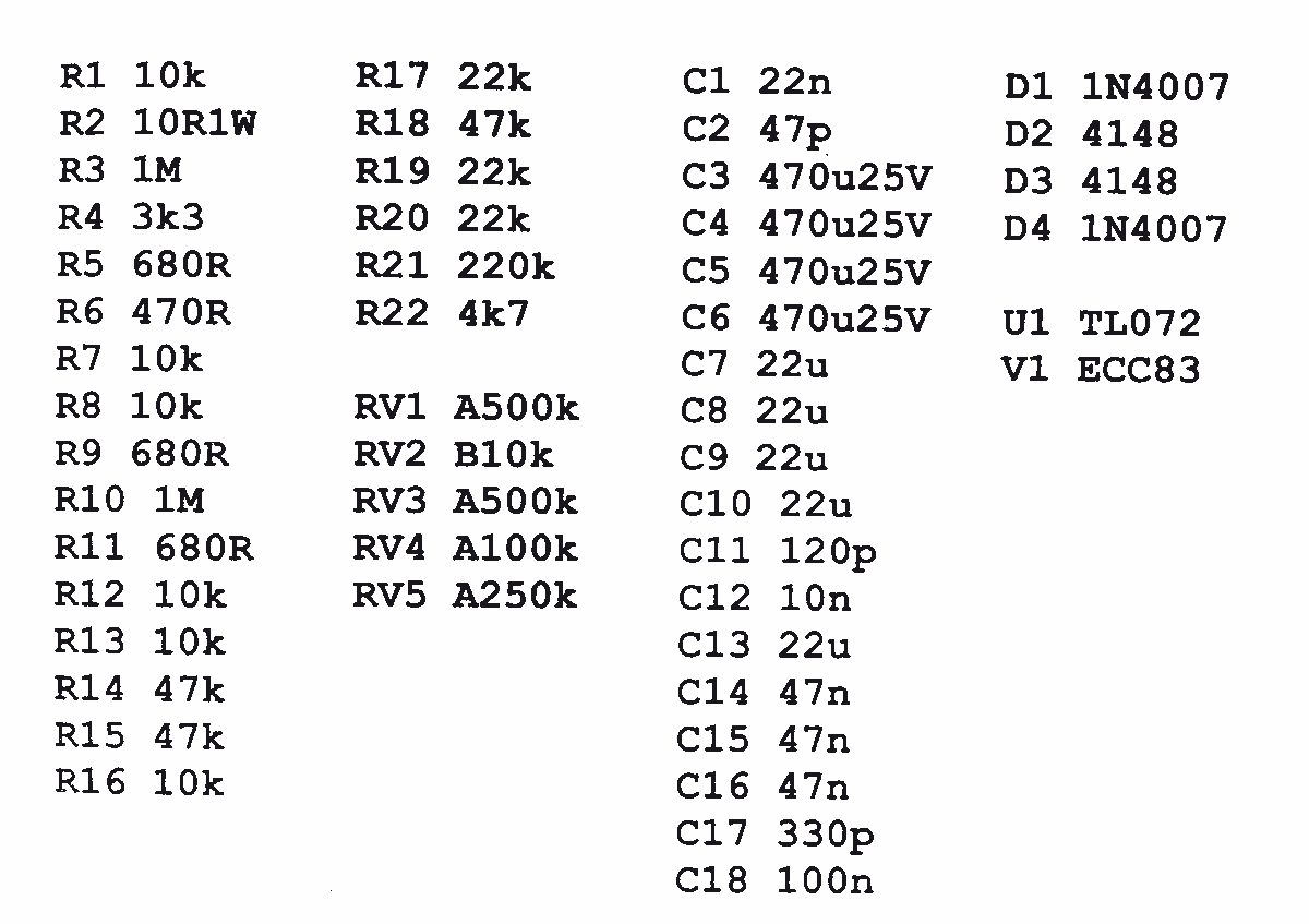
This circuit was copied from the original Tube Driver by user bajaman from the freestompboxes forum back in 2007, and over the years it has proven to be excellent.
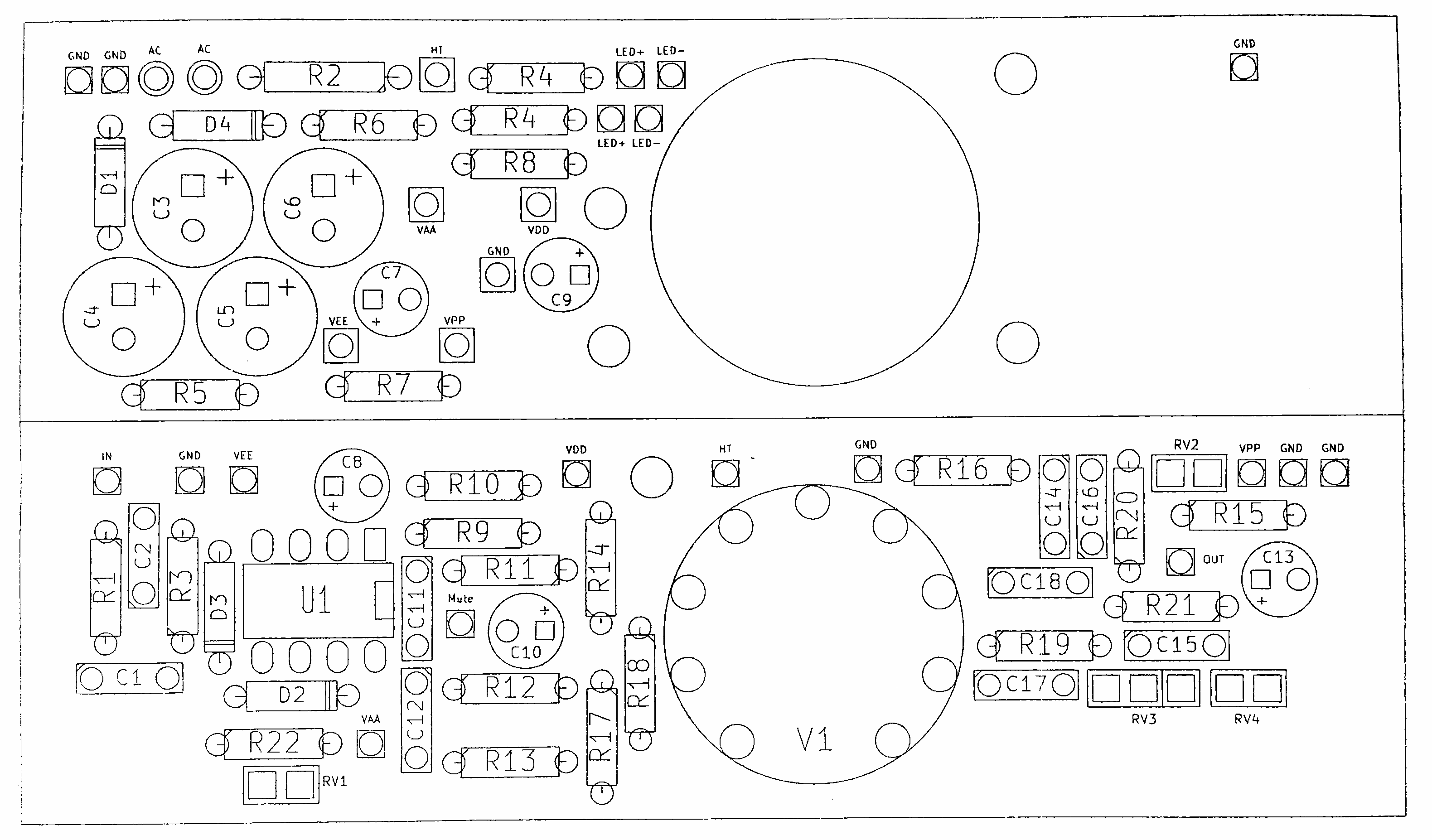
The values of some components differ from those specified in the patent, mainly for the purpose of increasing reliability. For example, capacitors for power supply are rated at 25 volts instead of 16, and film capacitors Orange Drop are used instead of electrolytics. In other words, the ideology is fully preserved, and the quality of the components is even improved.
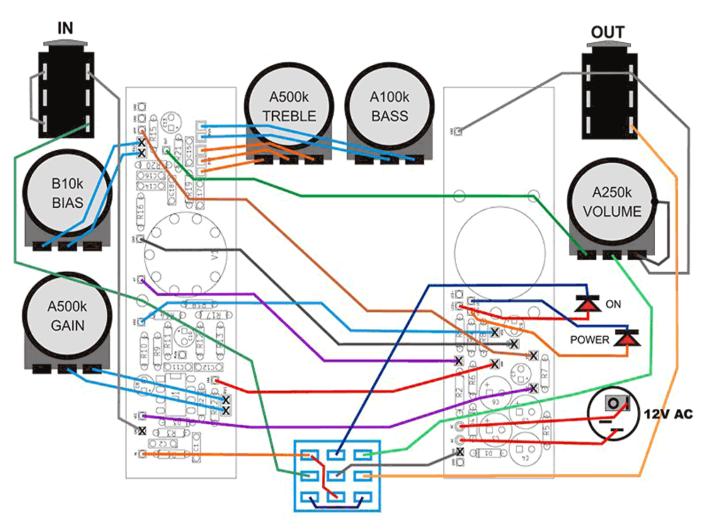
Where to Buy BK Butler Tube Driver DIY Parts
Since we got rid of the internal transformer, there is no need for a case as large as the original. We will use a standard 1590BB case and pre-made electronics with wiring specifically designed for this case, as shown in the above diagram, and buy a power supply for about 2 bucks at the nearest flea market (it's basically just a transformer in a separate case, so any 12-volt AC output will do). In addition, we will need brass standoffs to secure the boards inside the case, a drill, drill bits of 3mm, 5mm, 7mm, 10mm, and 12mm, and, of course, a 12AX7 (ECC83) tube.
What needs to be ordered:
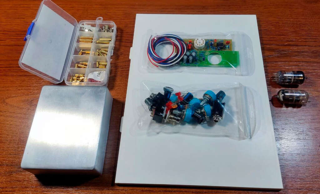
- A kit for DIY assembly of the BK Butler Tube Driver.
Includes two assembled boards for mounting in a 1590BB enclosure, plus a complete set of wires and connectors, LEDs, potentiometers, and a button.
Sold here. - 1590BB enclosure.
Sold here. - 12AX7 tubes.
I purchased ECC803S tubes from JJ and 12AX7 tubes from TJ Fullmusic. The first is a well-sounding and time-tested tube, while the second, according to many musicians, is the best Chinese-made tube; I just wanted to hear it.
Sold here and here - Stands for fixing the board inside the enclosure.
I prefer to use brass stands because they can be easily unscrewed when replacing the tube or op-amp. It's not easy to do with plastic clips, and besides, screw caps outside the enclosure look much nicer than plastic clips. I bought a whole box of different ones for the future, but in principle, we only need 6 pieces that are 5 millimeters long.
Sold here. - If you have a drill with drills, a soldering iron, flux, and solder, then all that's left is to mark the enclosure, fit, cut and strip the wires, connect 20 points on the board with a similar number of points on the second board, connectors, and potentiometers, and then assemble everything.
Assembly of BK Butler Tube Driver in old TV-box case
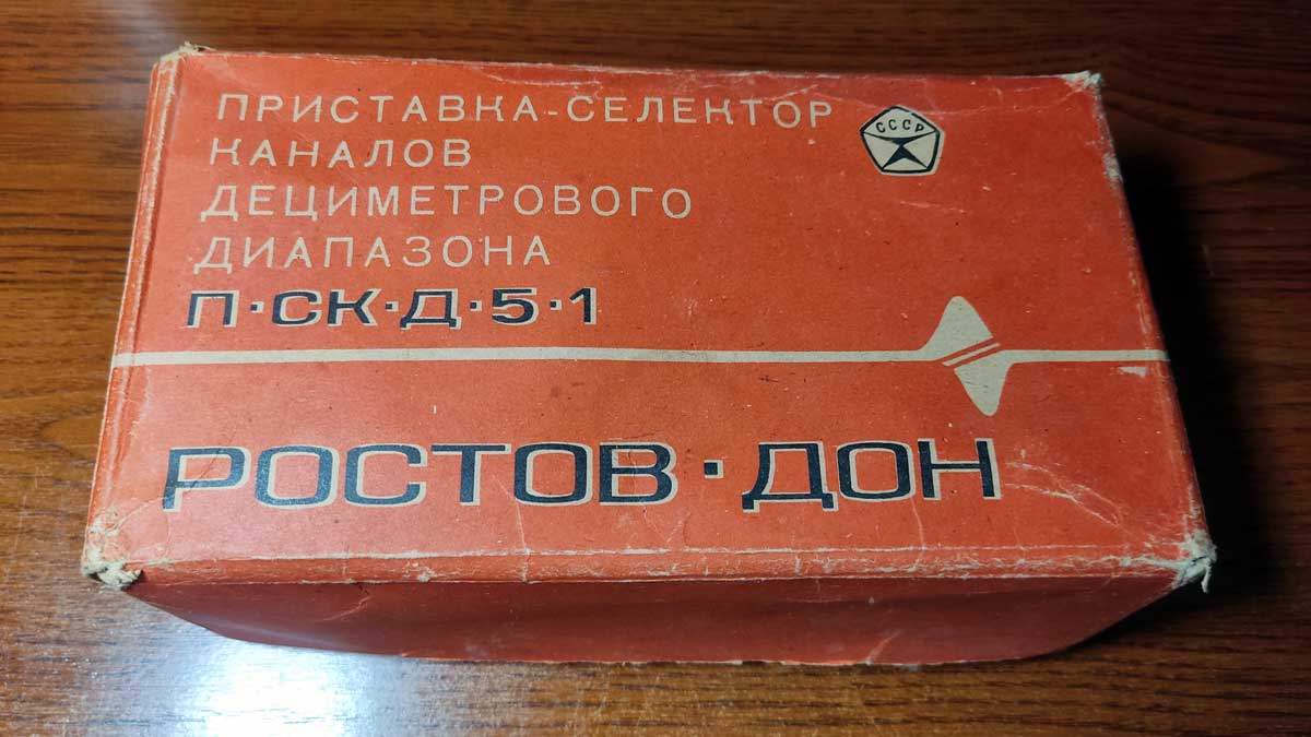
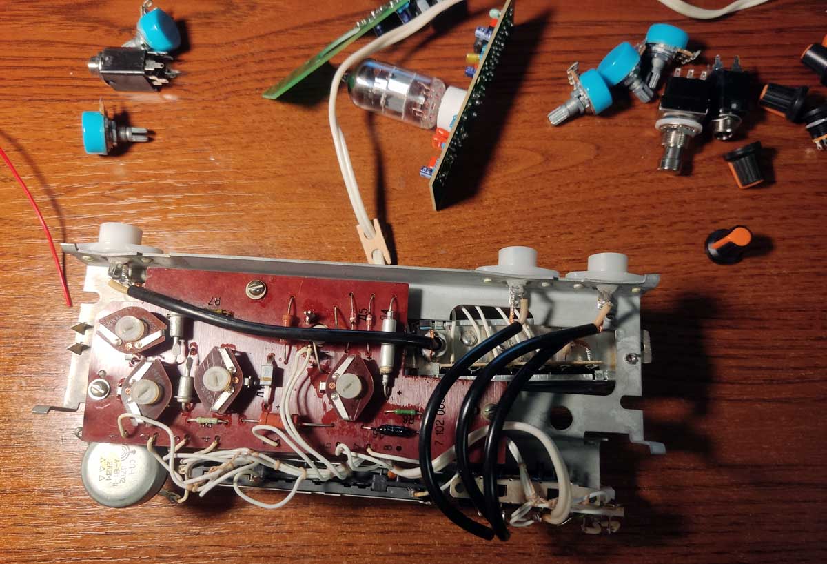
I wouldn't say that I didn't believe in success, but to begin with, I decided to save on the power supply and the case. By chance, I found the ancient 1970 TV-box in my workshop, and the main joy was that this box was powered by the transformer with a 15-volt output, just like the original BK Butler. It also had a power switch with a power-on indicator, antenna inputs on the rear panel that could be used for guitar jacks, and an already built-in 10kΩ potentiometer for bias adjustment. "A ready-made case with power supply for my DIY project," I thought, and got to work.
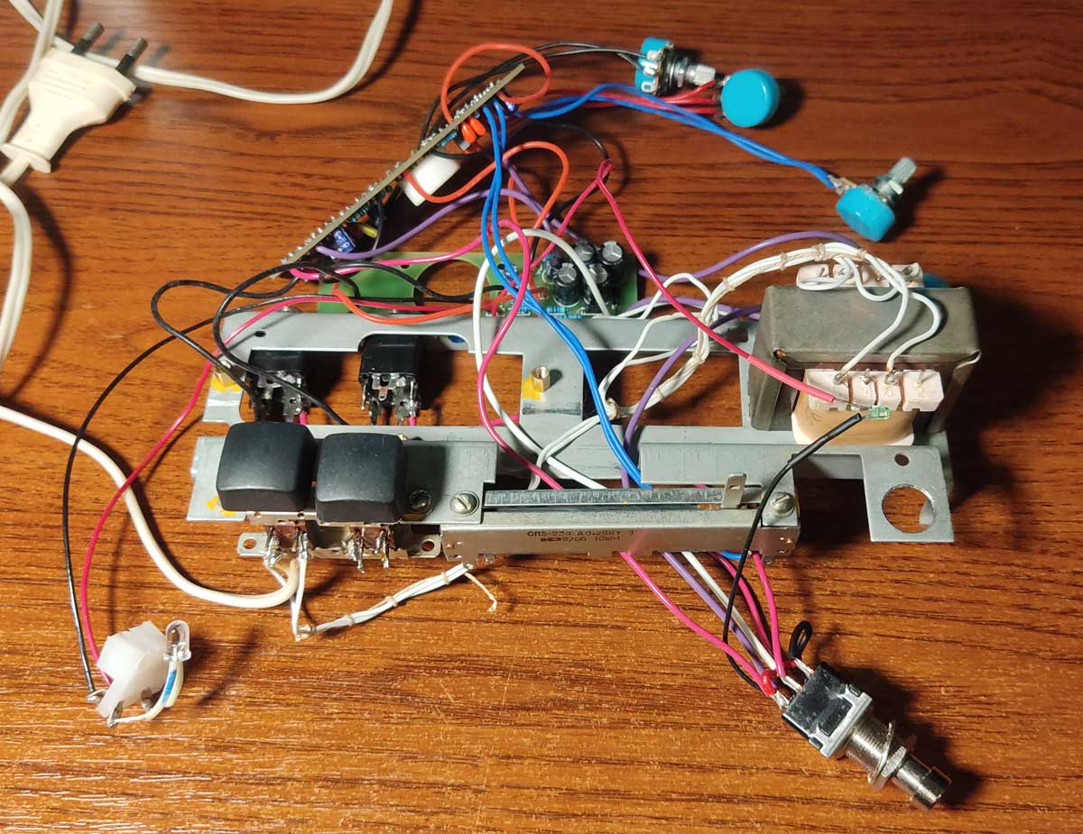
Open the case. Out of all this variety, we only need the transformer, power on/off buttons, and slider resistor. Everything else we mercilessly unscrew, drill out, pry out, and cut off.
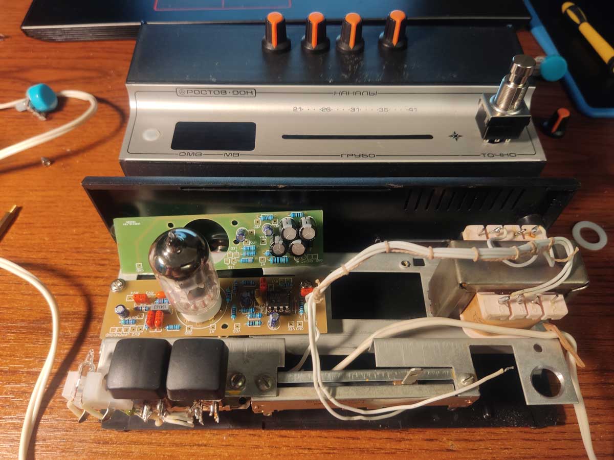
I place the boards and check the fit for determine the locations of the jacks, button, and knobs. The board with the tube is mounted on the standoffs in place of the original board, and one hole will need to be drilled in the board. The second board, where the power supply is located, will be screwed onto the standoffs directly to the back wall of the enclosure.
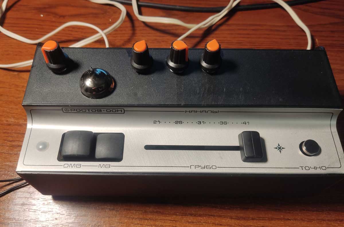
On the chassis need to drill holes. On the back where the antenna sockets were, for the guitar input and output - up to 10 mm, and for the power - 12 mm. On the top, instead of the "Fine" potentiometer, I'll set a switching button, 12 mm. I won't drill the body itself, the diameter of the holes in it is quite suitable. I place the potentiometers on the top of the body, with a diameter of 7 mm, mark and drill. We also need to make a hole for the lamp, I drilled a hole with a wood drill bit of 22 mm and then expanded it with a utility knife. The resulting hole is about 25 mm. This hole, firstly, simplifies the placement of the board in the body, and secondly, greatly simplifies the replacement of the lamp. By the way, I tried using an RFT ECC81 instead of the 12AX7, the sound is far from the original, but still very interesting.
Okay, let's remove the cover and start soldering. Usually, I solder circuits following the signal path, but this time I decided to follow the instructions and go clockwise. I started with the jumpers on the button, and then proceeded counterclockwise: the orange wire from R1, then ground from the input jack, and so on.
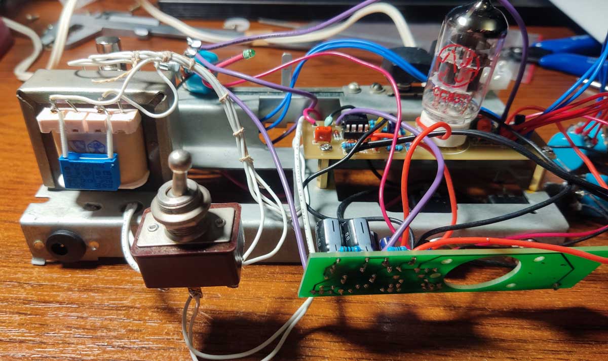
As a result, we got this frankenstein. I foresee comments like "the wires need to be shorter!" and "twist them into braids!", but I remind you that this is just a prototype for now. In the end, everything will be shortened and twisted, for now I just wanted to make sure that the circuit works. And it turns out that it really does work! I spent two evenings just extracting sounds that gave me goosebumps.
But the noise... To be honest, the original Tube Driver was not a great symbol of silence either, its signal-to-noise ratio was only 70dB. But here the noise was even higher. "The transformer is causing the noise," I thought, and immediately decided to make a duplicate external power supply. To make it easier to compare, I installed a military toggle switch that quickly switches the power supply from internal to external.
And to ease my conscience, I also soldered a parallel X2 capacitor to the input winding of the transformer. Do you know what changed? Nothing. When switching from the internal transformer to the external power supply, the tone of the noise changed, but not its volume. The next step is to shield the enclosure.
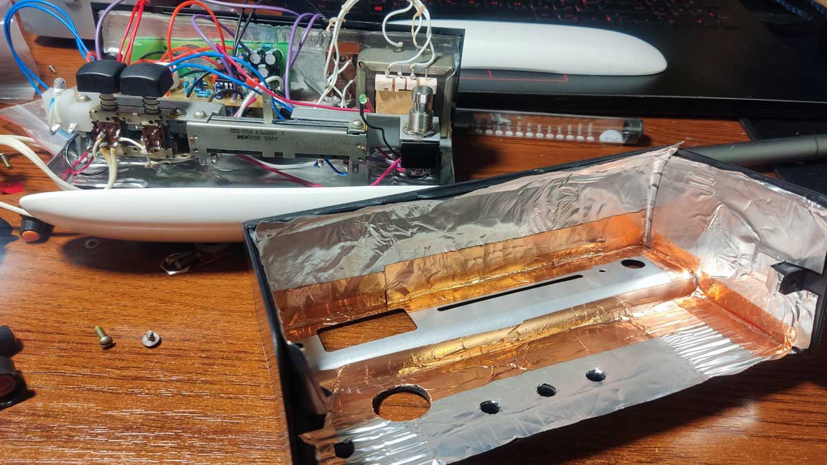
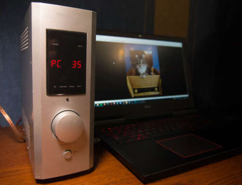
I am assembling and listening. When powered by the internal transformer, there is still some noise, although it is insignificant: you won't be able to play concerts with it, but it's fine for home use. And with the external power supply, the sound is absolutely wonderful. Clean, without noise or artifacts. To show off my work, I'm shipping the resulting device by post to a composer friend of mine. His name is Max, he composes music for movies and records it in his home studio.
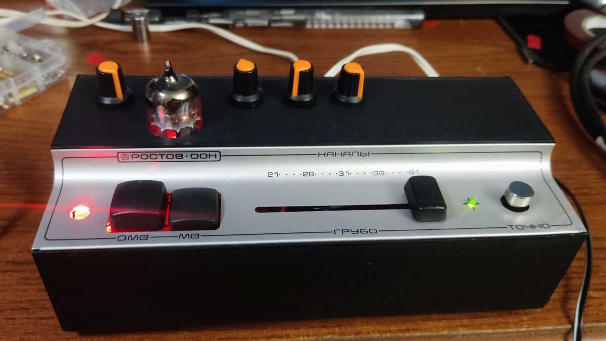
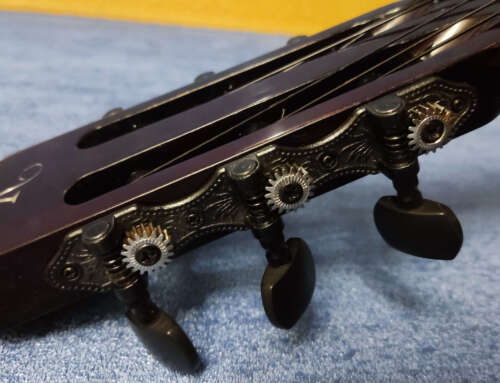
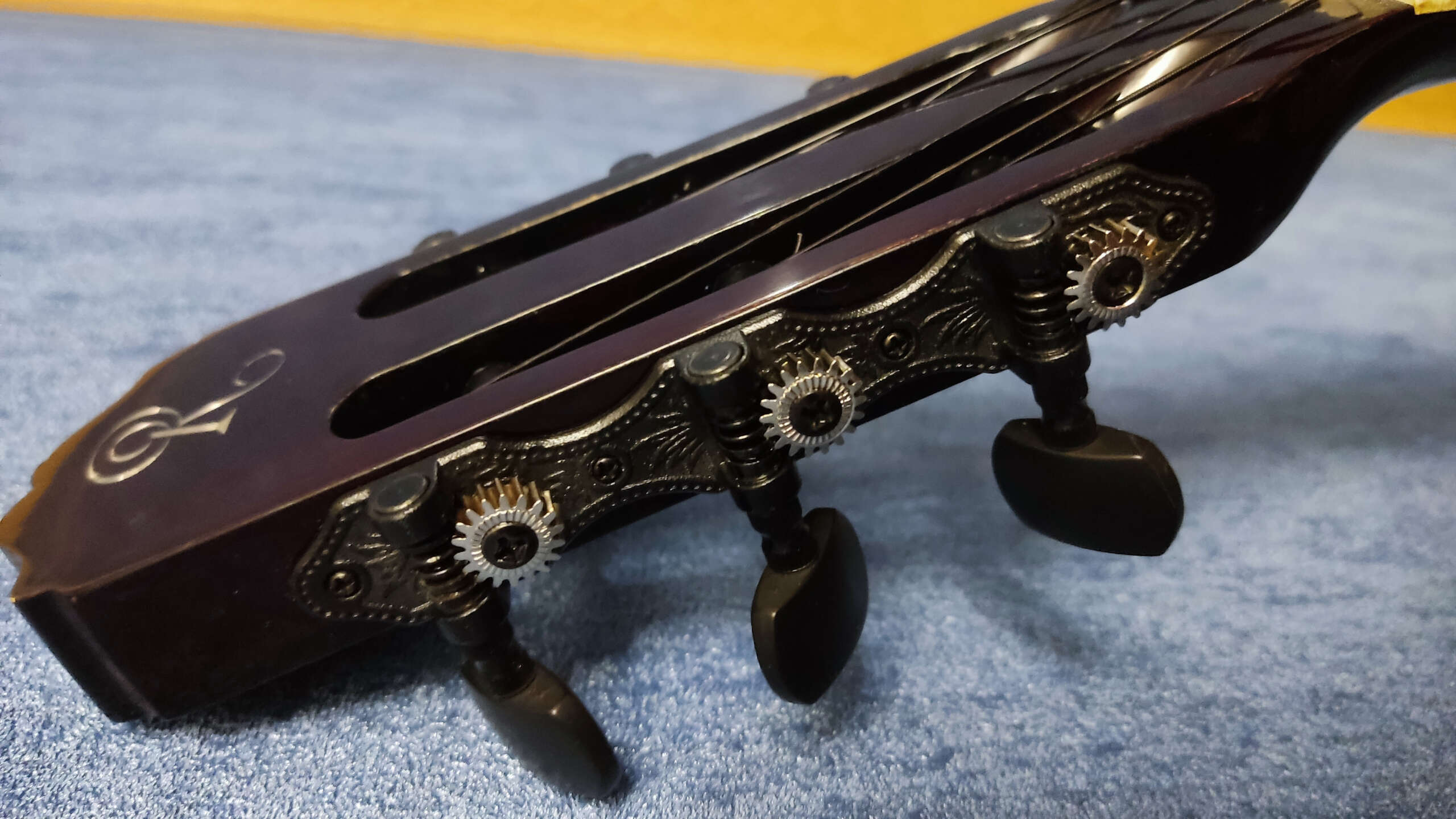
Two days after receiving the package, Max contacted me and called me a jerk. Because instead of working, he spent two days with his guitar and my pedal. And he's never heard a more beautiful overdrive in his life. And he asked me how much this thing costs because he's not returning it. I suggested completing the project, installing the boards in the casing, painting it, and making it look nice, but Max refused. First of all, he loves old school and steampunk, secondly, the sound is more important to him in the studio than aesthetics, and finally, he has no intention of using this device for concerts. And if he ever does, it's even cooler in its current state, whoever sees it will be greatly surprised.
In general, we agreed that the trial unit will remain in the studio, and instead, Max will order another set of spare parts, a tube, and a 1590BB aluminum enclosure for me. He also promised to record a demo of my version of Tube Driver.
The attack of Russia on our homeland delayed the release of the demo a bit, but it's recorded, and all the guitar parts on the track were recorded using the gadget described in the article.
Glory to Ukraine!