Microlab Pro Amplifier: What Is It and Why?
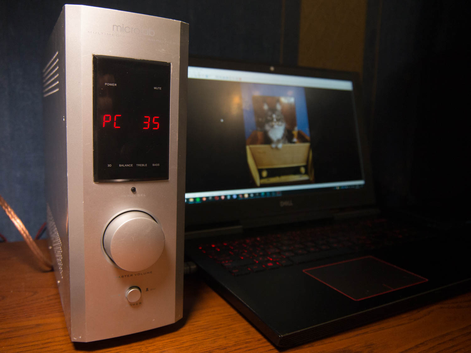
The Microlab Pro amplifier (I don't specify the model number because models I, II, and III are identical) came into my possession by chance when a composer friend asked me to repair it. When I asked why specifically the Microlab Pro, he gave two reasons. The first: he already has this amplifier and doesn't want to buy another. The second reason: the Microlab Pro sound can be described as "average hospital level"—neither bad nor good, just typical sound. The thing is, this particular amplifier was supposed to be used with Avantone Pro MixCubes reference monitors, which are intended to mimic an "average" acoustic system. By listening to music through reference speakers, the composer understands how his works will sound in car stereos, computers, televisions, and other household sound sources. Therefore, overall, he was satisfied with the Microlab Pro's sound. He was only displeased that after the previous repair, the amplifier started to "pop" when turned on. And he also told me, since I understand electronics, to check the circuit and make sure everything works as it should.
Technical Specifications and Features of the Microlab Pro Amplifier
Output power 2x30 W
Frequency response 45-20,000 Hz
Signal-to-noise ratio 65 dB
Channel separation 40 dB
These are the official data for the Microlab PRO 1 model. According to the manufacturer, the PRO 2 model has a power of 2x35 W, and the PRO 3 model boasts as much as 2x45 W. But this seems to be a marketing ploy because the amplifier's electrical schematic shows that it is common to the "pro 1, 2, 3" models. There are several schematic solutions for the amplifier; I've even come across an amp board based on a pair of TDA7265s in a bridged configuration, but the most common version is based on the LM4766 chip.
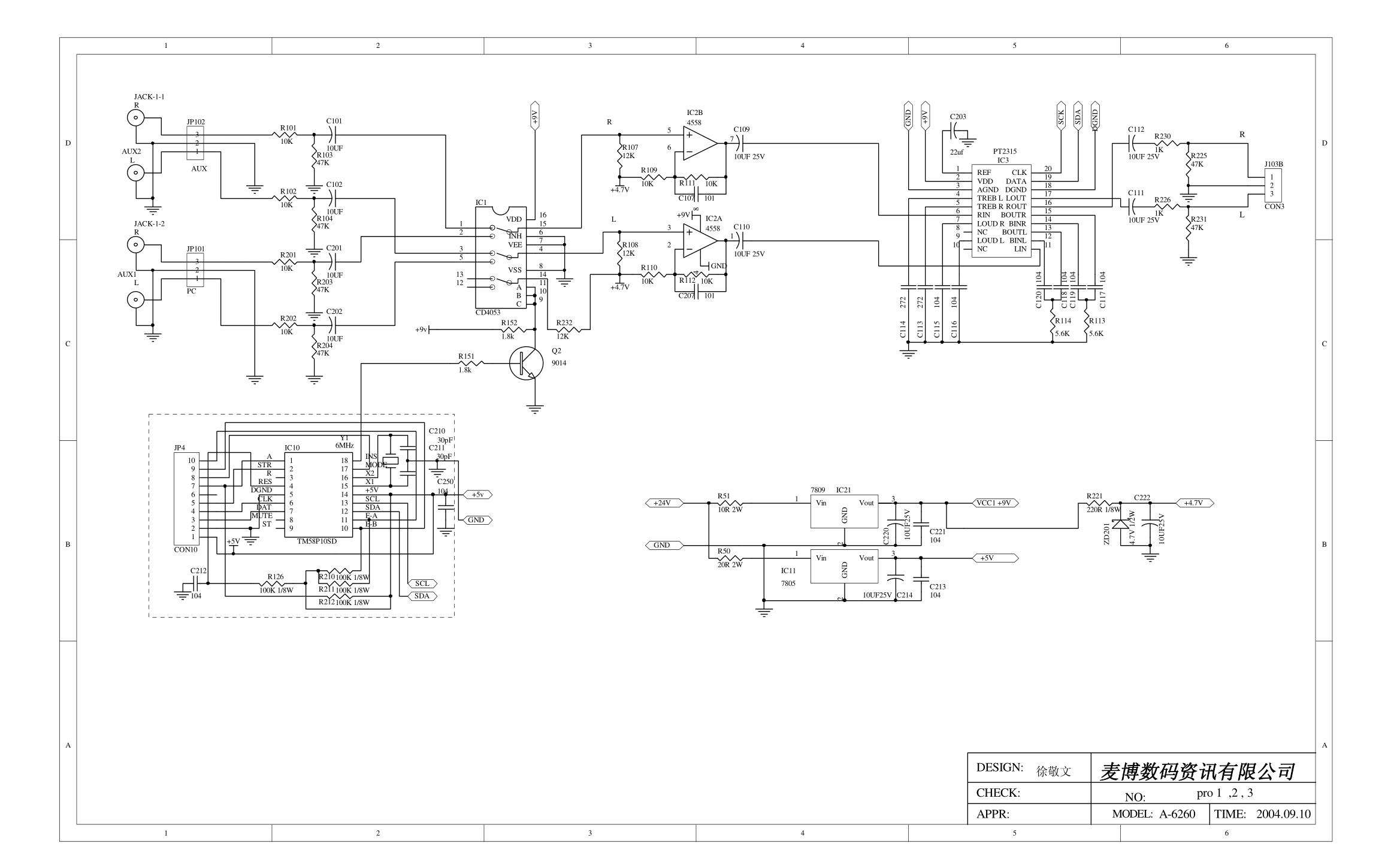
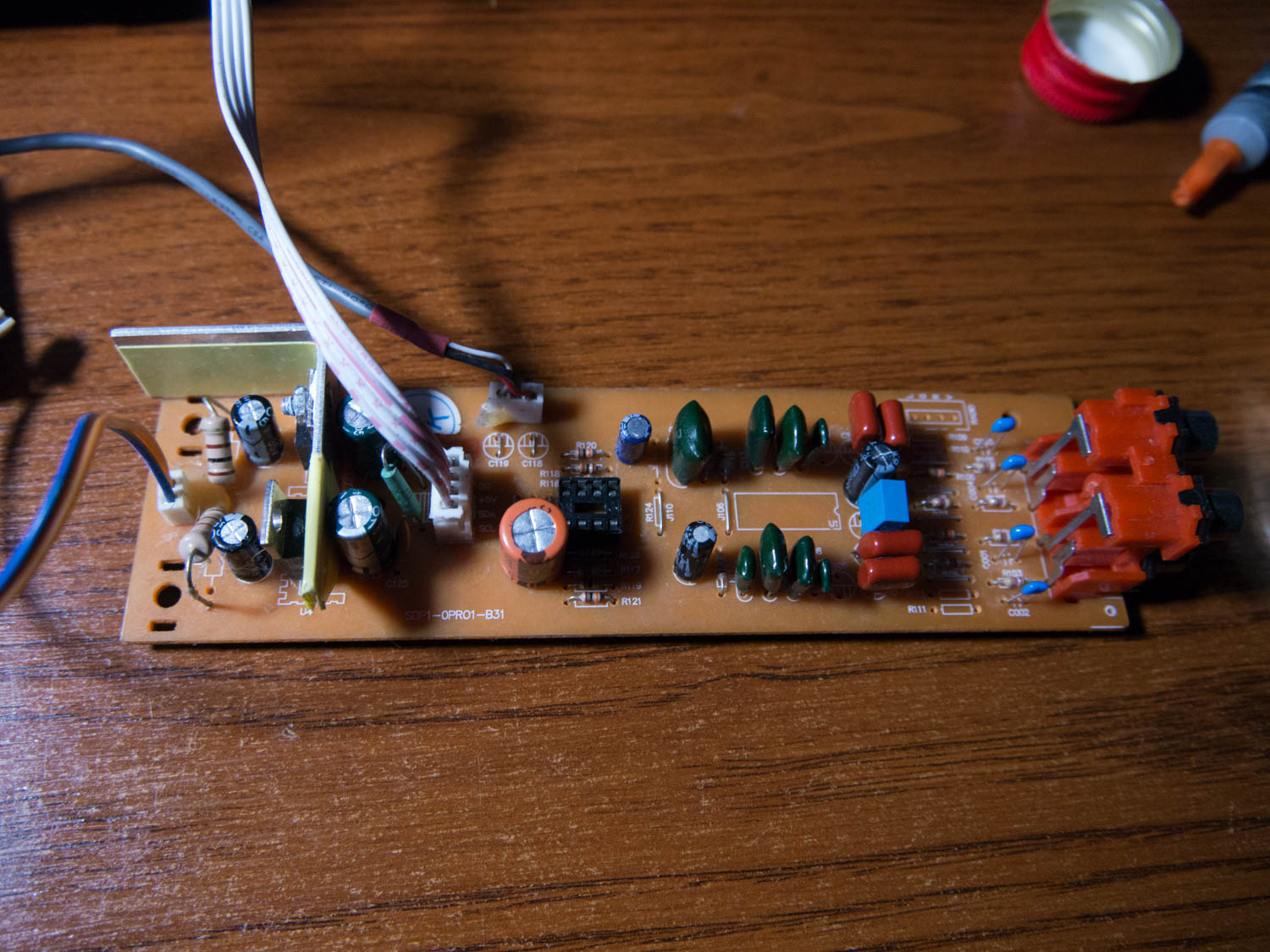
So, according to the schematic, the incoming signal goes to the SDP1-0PRO1-B31 preamp board. We have input filters C001, C002, C003, C004, through which the signal goes to the YG4558 operational amplifier (terrible), and from there to the R2S15900 audio processor, controlled by the TM58P10SD microcontroller, which also controls the display. Power comes from the amplifier board (24V) and is converted by voltage regulators LM7805 (5V for powering the processor and controller) and LM7809 (9V for powering the operational amplifier). It would be possible to do without the operational amplifier, but the R2S15900 processor reduces the signal level, so additional amplification is necessary.
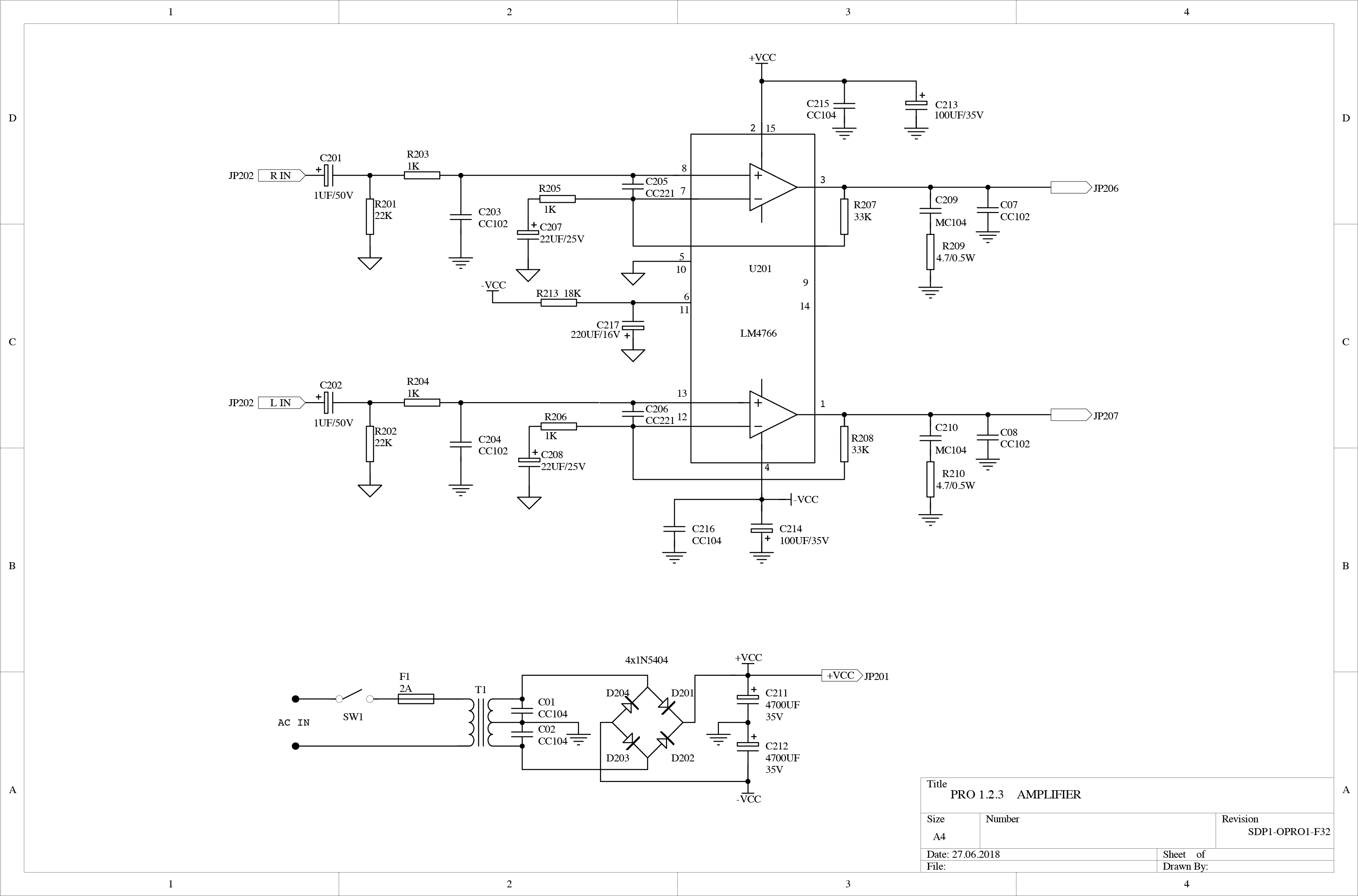
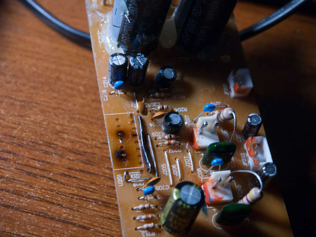
Next, through decoupling capacitors C111 and C112, the signal goes to the SDP1-0PRO1-B32 amplifier board, where it encounters another pair of decoupling capacitors C201 and C202. Here, I became suspicious. It turns out the circuit designers didn't bother much. They took the typical R2S15900 application circuit from the datasheet (where, of course, the output is a decoupling capacitor), took the LM4766 circuit from another datasheet (where the input also has a decoupling capacitor), and without thinking that this is the same capacitor, simply combined the two circuits and launched the product into production.
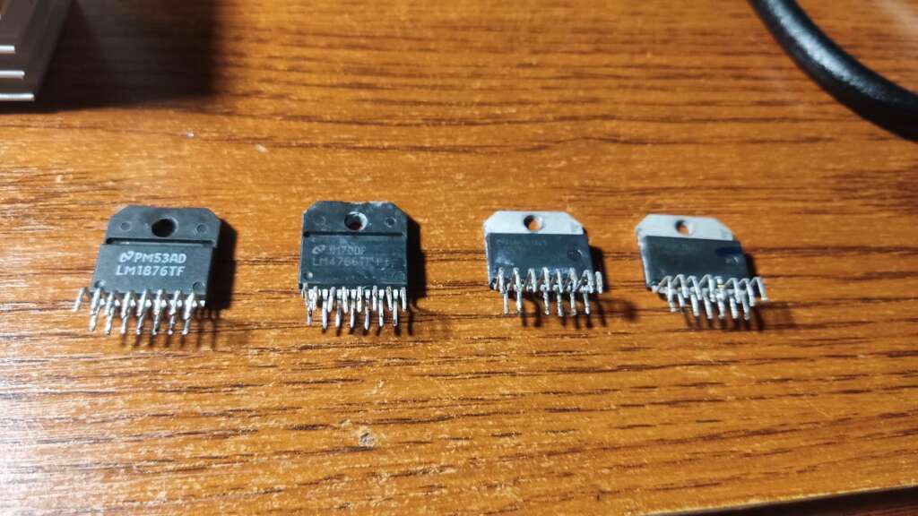
The power amplifier board does not hold any surprises, but the board I received had already been repaired. And it turned out that instead of the LM4766 amplifier chip, an unknown craftsman installed the LM1876TF chip, which is pin-compatible.
This was the main problem. The anti-pop protection mechanism at power-on in the LM4766 chip is implemented using capacitor C217 on pins 6 and 11, which is connected to V- through resistor R213. At power-on, the capacitor is discharged, and the chip is in Mute mode, but when the capacitor charges, the chip exits Mute mode.
Here I was surprised again by the Chinese circuit designers who installed a 16-volt capacitor. Naturally, this capacitor was dead, but even replacing it with a new 330uF 35v capacitor didn't help because the Mute mode activation in the LM1876TF chip is implemented differently. In other words, to fix the main problem, it was necessary to return the original chip and make sure the speakers didn't pop at power-on. And only then proceed to tuning.
Microlab Pro Amplifier Repair
Since I consider ordering radio parts from AliExpress a lottery, and the amplifier needed to be repaired, I approached the process creatively. First, I ordered the cheapest LM4766T chip for $1.50. Second, I ordered an LM4766TF (the same chip but in a plastic case). Why the second one? So I wouldn't have to bother with installing a heatsink pad because the chip's power supply is bipolar, and the heatsink is not grounded. And just in case, I bought a ready-made amplifier board on the same chip. The fact is that the condition of the factory board left much to be desired. The original LM4766T chip had burned out, physically burning a piece of the board with traces. I managed to desolder the LM1876TF without increasing the damage, but if the ordered chips turn out to be defective, I will only find out after installing them. Will the original board survive desoldering and resoldering?
I also ordered thermal pads (suitable for TO-247), insulating washers (suitable for TO-220), and a handful of operational amplifiers TL072, TL082, JRC4580DD, 4559, and three types of 5532, from NJM, TI, and Philips, as well as capacitors, and also went to the nearest radio store for parts that I couldn't find online.
When everything arrived, it turned out that the cheapest chip was original, and the expensive LM4766TF was a repurposed LM1876TF, which still popped the speakers on power-up. I got my money back through a dispute, and in the meantime, I installed the LM4766T, soldering the broken traces to the chip with classic MGTF, and got an almost fully working amplifier. Almost, because the pop disappeared, but the first five seconds after power-on, the amplifier made a nasty crackling and grunting noise.
Microlab Pro Amplifier Modifications
There is an opinion that Microlab PRO amplifiers with live capacitors no longer exist today: they weren't very high quality to begin with, and now there's age. Using an ESR meter on the schematic, I confirmed that this is true; there were only four live electrolytic capacitors left in the entire circuit. For upgrading the Microlab PRO amplifier, let's first go through the power supply and then follow the sound path from the input to the speakers.
First, replace the power supply capacitors C211 and C212. I installed Nichicon 35V 6800UF 18x40mm. You can also replace the rectifier diodes with Schottky diodes; I even bought four SB5100s, but didn't install them because the result was satisfactory without them.
Replace capacitors C01 and C02 with multilayer ceramics. I used Hitano.
Replace capacitors C213 and C214 with new ones (I installed 220uF 35V), and C215 and C216 with multilayer ceramics.
Move on to the preamp board. Replace C120 and C121, C122 and C125 with new ones. The datasheet specifies 0.1 and 0.33uF, so you don't need to increase the capacitance.
Near the power connector of the front panel, there's a ferrite bead L101. Replace it with an inductor of appropriate size up to 1000uH, and also replace the low impedance capacitor near the volume knob (I don't remember the number) on the front panel board. This will help eliminate high-frequency noise that may come into the 5-volt power line from the digital display on the front panel.
It's very important to replace C126! This is the power supply capacitor for the R2S15900SP chip, and it was responsible for the crackling and screeching after the amplifier was turned on. I replaced it with a 10uF LowESR, and the noise disappeared.
C107 is the reference voltage capacitor for the R2S15900 audio processor, replace it with a film capacitor (MEB 1uF 63VDC Hitano).
I installed a heatsink on the LM7809 regulator. Not that it's really needed, but just for peace of mind.
Power supply completed. Now on to the sound.
Replace the filtering ceramic capacitors C001, C002, C003, C004 with multilayer ceramics. I used 1nF 50V NP0 Hitano.
Replace the input decoupling capacitors C101, C102, C103, and C104 with good film capacitors, such as MEB 1uF 63VDC (they fit perfectly in size).
Replace C118 and C119, which are on the output, with wire jumpers. These capacitors are not needed because the signal from them goes to the amplifier board to capacitors C201 and C202, which perform the same function.
The remaining electrolytic capacitors on the preamp board are simply replaced with similar but new and high-quality ones.
Move on to the amplifier board. The mentioned C201 and C202 I replaced with Samwha LowESR WL series capacitors. I tried replacing them with polyester Hitano MEB, but got a muddy sound, so I returned the electrolytics.
C207, C208 I replaced with 22uF 50V KC3 Koshin. You could install 35-volt ones, but the 50-volt ones have lower ESR.
C213, C214 - amplifier chip power supply, install electrolytic capacitors rated at 35 volts with the maximum reasonable capacitance. I installed 220uF, you could install 330uF if they fit in the footprint.
The manufacturer-installed polyester C209, C210 is recommended to be replaced with polyester 0.1uF (CL21 or CBB). I tried it, noticed no difference.
I also desoldered the YG4558 operational amplifier and installed a DIP8 socket in its place, and when all the ordered operational amplifiers arrived, I listened to them one by one. I liked the sound of the TL072 the most.
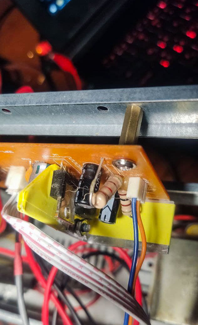
After detailed listening, I twisted the power supply wires into a braid, lubricated the encoder, cleaned the screen and the protective glass of the display, removed the detestable plastic clips and replaced them with nice brass standoffs, and then assembled the amplifier, preparing it for delivery to the owner. I hope he will be satisfied.
Does It Make Sense to Tweak the Microlab Pro?
For the purposes I described - absolutely. The amplifier didn't become high-fidelity equipment after the modifications, but the sound became clearer, the noise disappeared, and everything that should work, now works. It would be possible to go further: recalculating the operational amplifier's operating mode or eliminating the audio processor altogether, but in my opinion, the most significant improvements to the sound came from replacing the operational amplifier and removing the unnecessary pair of decoupling capacitors, while the noise reduction was achieved by installing an inductor and replacing the power supply capacitors. Further modifications would take more time than they would yield positive changes.
Is it worth doing? If you have this amplifier and want to improve the sound, then it's definitely worth it. If you're considering buying a Microlab PRO amplifier to tweak and use, it's also an option, although even now the Microlab PRO's price on the secondary market exceeds its consumer qualities. But if you're thinking about buying a Microlab PRO set with speakers, I wouldn't recommend it.
